I’ve been building electric guitars and basses for about four years. For a while, I’ve wanted to use that knowledge to build an acoustic guitar. Building an acoustic has always felt quite daunting as the process utilizes even more specialized jigs and tools than electrics do. In contemplating an acoustic build, I worried I would invest in the new tools, not enjoy the process of acoustics, and have wasted money on equipment I no longer need.
As I planned things out I made the decision to make as many of the jigs/tools I need. The number one reason being to keep costs down. Sure, there are ways to build an acoustic with a minimal amount of jigs/tools but for me I want to have the precision that jigs provide. Jigs also make the process more easily repeatable if I decide I want to continue building acoustics. Since 3D printers and a laser cutter are tools in my workshop, I decided I would utilize them as much as possible for the Jig building. These machines provide precision that I myself cannot attain easily. Also, it’s nice to have a robot build for you while you sleep!
To start off I found many helpful resources, which included the following and more:
Books: Build Your Own Acoustic Guitar, Guitar Making For The Small Shop
YouTube: Gabriele Reti, OBrien Guitars, The Pragmatic Luthier
Blog: Guitar 101 - Larry Heffner
For my build, I’m basically following the plan provided in the Build Your Own Acoustic Guitar book. The author, Jonathan Kinkead, calls this guitar the Kinkead Kingsdown Steel String. The best I can tell, it’s roughly the size of a common OM model.
Jigs/Tools Needed:
Steambox Build
If you’ve looked into building an acoustic guitar you’ve probably found there are at least 3 ways to bend the sides.
I chose to go the steambox and mold route. I mostly followed this video when It came to building the box.
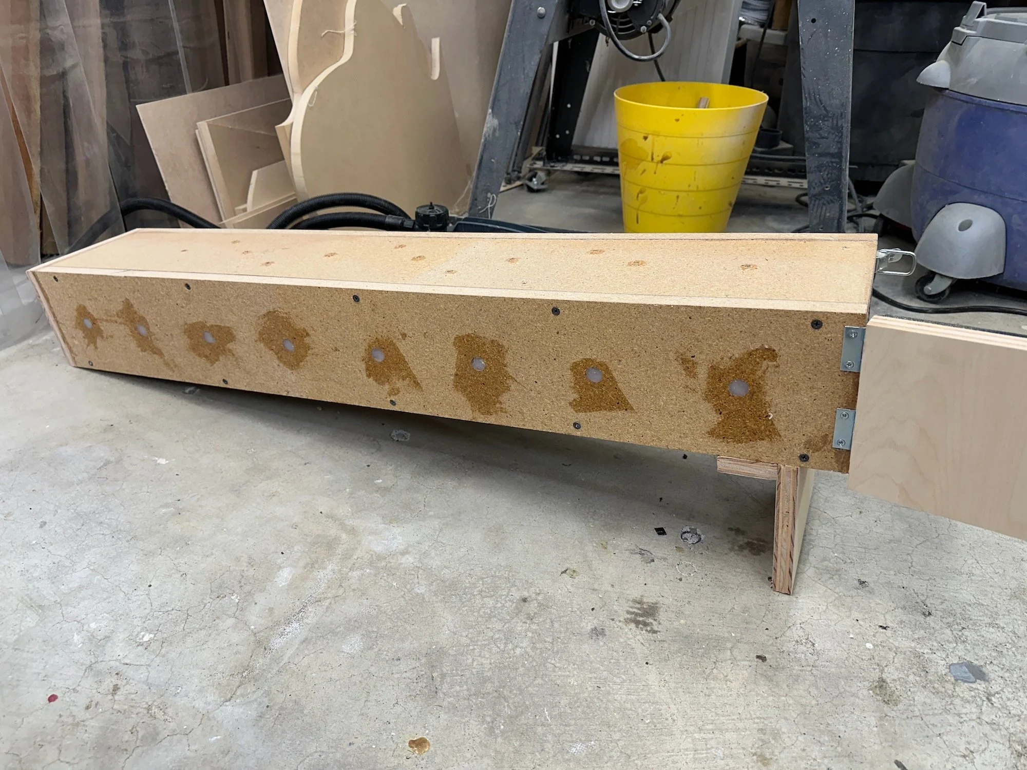
The box is about 42” x 7.5” x 6” in size. For the main material I repurposed an old kitchen countertop I recently removed during my kitchen remodel. The “wood” is actually pressboard, which does not hold up well to moisture. Fortunately, the countertop still had Formica still attached to it which basically made one side waterproof. I won’t go into much more detail of the construction because it’s a basic box.
The main features include sealed to hold steam and wooden dowels placed across the midline for the wood to sit elevated so the steam can get to both sides of the board. I sealed all joints with silicone and well as the raw pressboard edges for some moisture protection. Holes are drilled into the top for pressure relief. The door end is elevated so the steam will flow to the opposite end. The steam unit came with a brass fitting to connect the steam hose to the box.
Side Bending Mold (Outside)
Since I decided on the steam box method it requires using a side mold for bending. This mold needs to be the size of the outside of the body shape minus the thickness of the side wood. I made mine at -2mm. Using Adobe Illustrator and Fusion 360 I created the 3D Model and printed it in PET-G filament. The bed of my CR-10 Pro printer is not big enough to print it in one piece so I had to split the model in two and weld them together. When I say weld I’m actually referring to heat melting the pieces together with a soldering iron and extra filament.
I did not take photos of the separate side prints so I added screenshots of the 3D models. The printed mold is screwed to a plywood base for support. As you can see, I was originally concerned about the heat affecting the PET-G surface so I covered it with aluminum tape. I eventually removed the tape so I could drill vent holes in the mold. I’ll write more about that later.
Full Shape Mold
I looked at many types of full shape molds, they are most commonly made from MDF. Since I already had plenty of MDF on hand, I decided to make mine the same way. I pretty much just copied this design. If I had not already had the material needed I would have just purchased one of these. Out of all of the costly apparatus you need, these particular molds are sold at a decent price. For accuracy sake I imported the Kinkade full plan into Illustrator and drew the vector shapes then cut router templates out of 1/4 plywood with the laser cutter. I 3D designed and printed the inner pressure blocks which are held in place by turnbuckles.
Radius Dishes
Radius dishes are commonly made from CNC’ed MDF. I don’t own a CNC so I again utilized my 3D printer with PET-G filament to make the 15ft (back) and 25ft (front) radius dishes. I hadn’t seen radius dish made this way before so I thought this would be a fun experiment. I had to print the dishes in quarters and weld them together. Welding the plastic can be a bit messy so you can see I cleaned it up with sanding. Once they were one welded together I noticed the centers lift up. I adhered each dish down to a flat piece of 3/4” MDF to make sure the back was completely flat. For the sandpaper I purchased the 80grit 24” sticky back sanding discs from Red Label Abrasives, which had the lowest price I could find.
Go-Bar Clamping System
For the Go-Bar clamping deck I had two design goals: utilize scrap materials and make it easily break-down-able (for shop space saving). Instead of using all-thread (most common) for the stanchions, I repurposed some old 2x4’s. I 3D designed and printed upper and lower end-brackets for each stanchion that the 2x4’s could easily be inserted and removed from. Combined with a peg and hole system the upper deck is height adjustable, depending on the thickness of the items being clamped. The bottom deck is two sheets of 3/4 MDF adhered together, the top is one sheet. The length and width of the deck is 24” x 24”, maximum height is about 30”. For the flexible clamping bars I purchased these fiberglass rods and extra end caps. The rods are simply cut in half.
You may have noticed I haven’t mentioned the Binding Router Jig yet. I’m still working on this one so I’ll come back to it later once I have things figured out.
For now, I think I’m ready to start building a guitar.


