Needed: A Binding Router Jig
Do you remember at the end of Part 1 when I said I would come back to this?
There are several ways the rebate channels for the binding can be cut. The simplest method is by cutting and carving all by hand. That is also the hardest way and I am not a master woodcarver. The easiest way is by routing the edge with a rabbeting bit. Although it is an easy operation there is one large caveat with the routing option. The Soundboard and back are not square to the sides of the body due to the radius curve each has. This poses a problem since you cannot just simply run a router around the edge with it flat against the curved surface. The rebate cut would not be square to the sides and that would create problems when installing the binding.
The solution is to have a router jig that holds the router/bit parallel to the top edge and square to the sides. Several commercial binding jigs are available but they are also not inexpensive. So, naturally I set out to build my own. I had some leftover parts from an old 3D printer and laser cutter and I already own an older Dewalt trim router so there would be little investment beyond the printing filament and misc parts.
The design I decided to copy is the Binding Router Jig sold by StewMac. Seen below.
My original design for the carriage utilized the standard adjustable platform of the router. What I hadn’t realized was that the Freud rabbet bit I was using did not have a long enough shaft to work with the platform I designed.
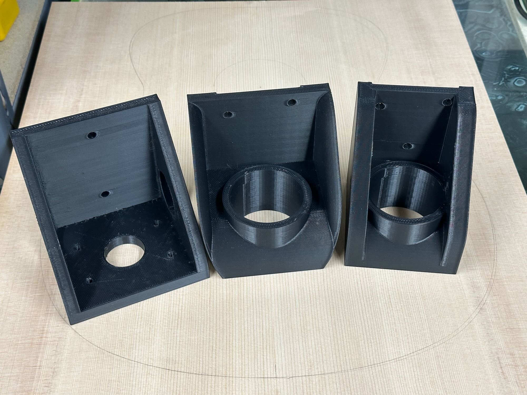
I went through three carriage designs before I settled on the last one (#1), on the far right. Due to the short bit shaft length I had to remove the adjustable platform from the router. Removing the platform meant I had to add a mount that was integrated in the carriage. This design was not ideal because it relied on the router housing to press fit into the carriage. While it did its job (securing the router to the carriage) it allowed no way to adjust the depth of the router without removing the router from the carriage first.
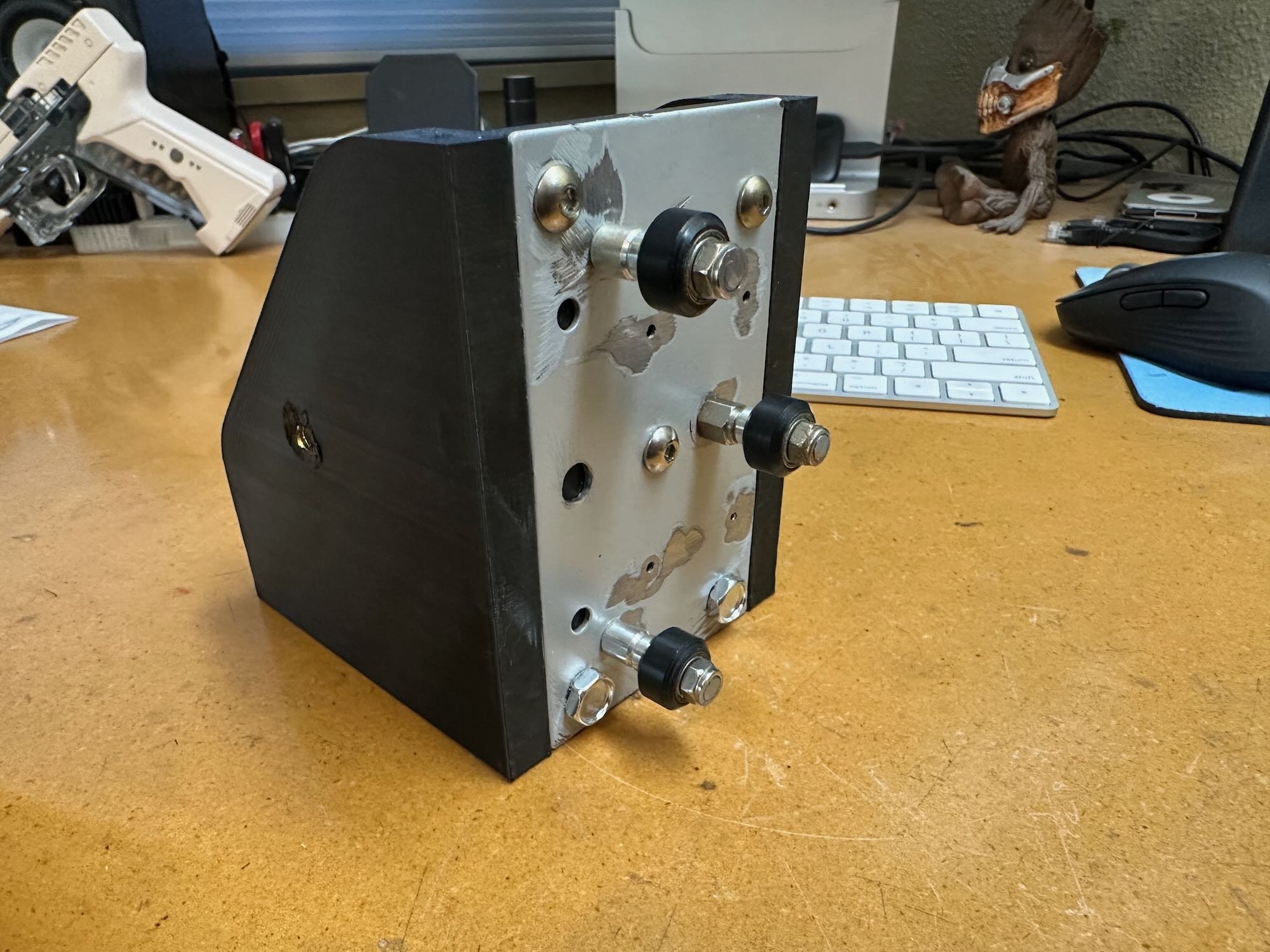
For the carriage mechanism slide, I used roller wheels and misc. parts from a dead laser cutter (#2). The aluminum extrusion rail was a piece leftover from a 3D printer. I also printed a right angle bracket that screw mounts to the table (work surface) and attaches to the base of the rail (#3).
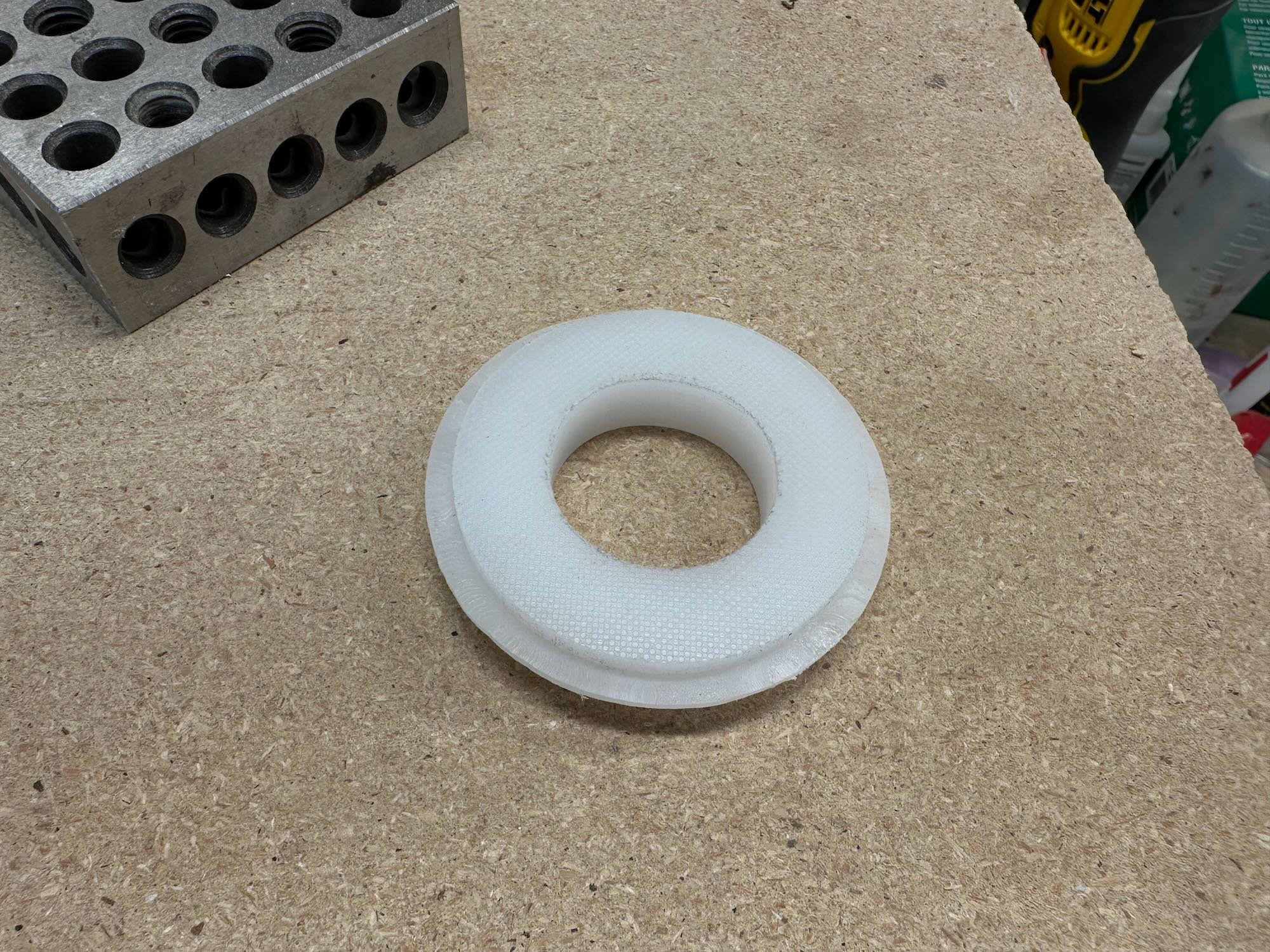
Probably the most crucial part of the carriage is a beveled teflon washer that surrounds the router bit. This is the part of the carriage that makes contact with the facing “up” part of the guitar body (Soundboard or back). The Teflon washer only has about ¼” ring that actually contacts the body. Since the router is on a roller carriage it moves up and down following the contour of the up facing part of the body, while the roller bearing on the Rabbet bit glides along the side of the body. I looked into purchasing an actual chunk of teflon but found it to be too expensive. Instead, I bought a cheap ¾” plastic cutting board and made the “Teflon” washer from it. While setting up the bit I learned I did not have a correct sized bearing for the bit to get the desired (shallow) depth I needed. To solve this problem I 3D designed/printed a thicker sleeve that press fitted over the bearing. This widened the bearing to the correct blade depth (2mm).
The second part of this jig is a body sled (#7). The body has to be secured in a way that aligns the “flatness” of the Soundboard/back and sides to relative squareness of the router/work surface. The sled assures the sides of the body are parallel to the router's up/down movement and provided a flat surface to slide against. The adjustable height brackets account for the un-flatness of the body. Correct placement is checked with a carpenters square holding one side of the square against the work surface and the other against the guitar body side. Squaring the body to the work surface is a bit of a dance between all four adjusters that requires multiple points of checking and adjustments.
To build the sled and adjusters, I use a scrap piece of MDF and 3D designed/printed the necessary L brackets and adjusters (#8). With all adjustments aligned the rabbet cut will be square to a relative 90° angle of the body (#9).
Conclusion
This was the most difficult to build jig for this project. All in all, it worked quite well. That said, I already have plans to build a 2.0 version which utilizes the Bosch Colt router (I already picked one up on a great black friday deal). The Colt has an adjustable platform design more suited for this jig. Hopefully, I will be able to create one that works as well AND is easier to adjust.


