Building An Acoustic Guitar For The First Time - Part 5: Making a Binding Router Jig

Needed: A Binding Router Jig

Do you remember at the end of Part 1 when I said I would come back to this?

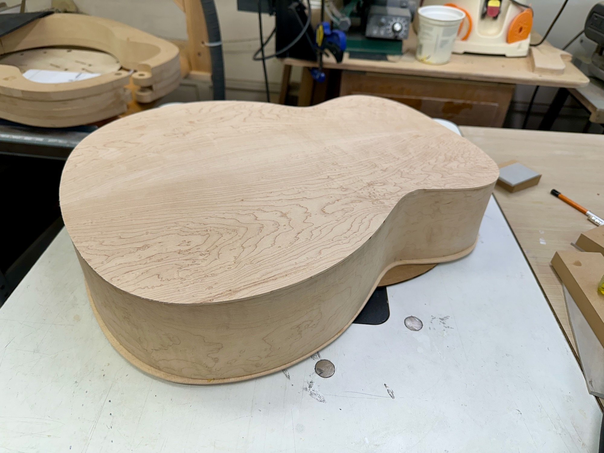
There are several ways the rebate channels for the binding can be cut. The simplest method is by cutting and carving all by hand. That is also the hardest way and I am not a master woodcarver. The easiest way is by routing the edge with a rabbeting bit. Although it is an easy operation there is one large caveat with the routing option. The Soundboard and back are not square to the sides of the body due to the radius curve each has. This poses a problem since you cannot just simply run a router around the edge with it flat against the curved surface. The rebate cut would not be square to the sides and that would create problems when installing the binding.

The solution is to have a router jig that holds the router/bit parallel to the top edge and square to the sides. Several commercial binding jigs are available but they are also not inexpensive. So, naturally I set out to build my own. I had some leftover parts from an old 3D printer and laser cutter and I already own an older Dewalt trim router so there would be little investment beyond the printing filament and misc parts.

The design I decided to copy is the Binding Router Jig sold by StewMac. Seen below.


My original design for the carriage utilized the standard adjustable platform of the router. What I hadn’t realized was that the Freud rabbet bit I was using did not have a long enough shaft to work with the platform I designed. 

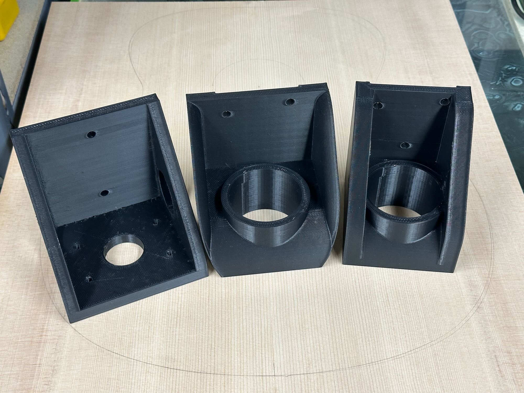
I went through three carriage designs before I settled on the last one (#1), on the far right. Due to the short bit shaft length I had to remove the adjustable platform from the router. Removing the platform meant I had to add a mount that was integrated in the carriage. This design was not ideal because it relied on the router housing to press fit into the carriage. While it did its job (securing the router to the carriage) it allowed no way to adjust the depth of the router without removing the router from the carriage first.

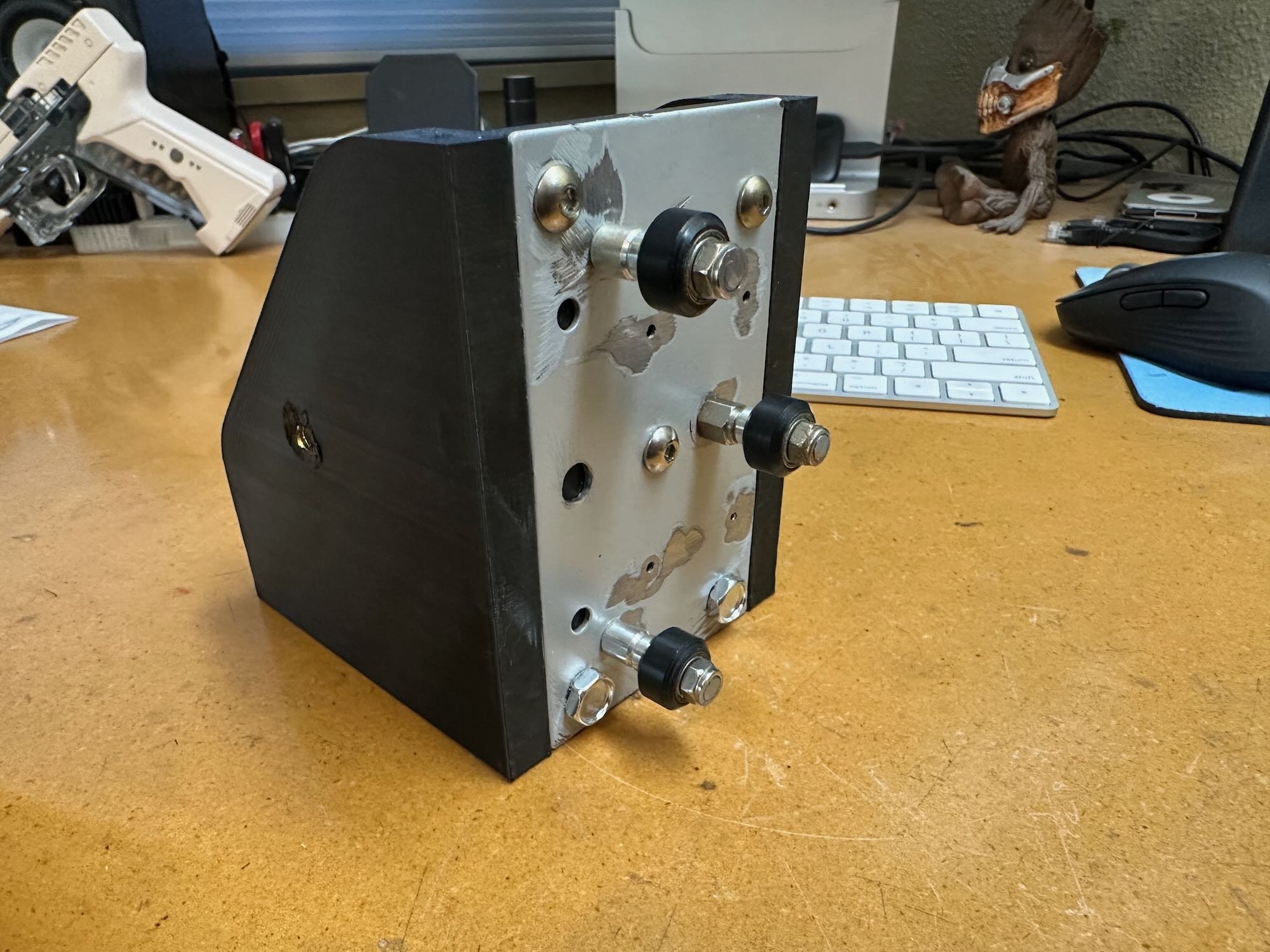
For the carriage mechanism slide, I used roller wheels and misc. parts from a dead laser cutter (#2). The aluminum extrusion rail was a piece leftover from a 3D printer. I also printed a right angle bracket that screw mounts to the table (work surface) and attaches to the base of the rail (#3).

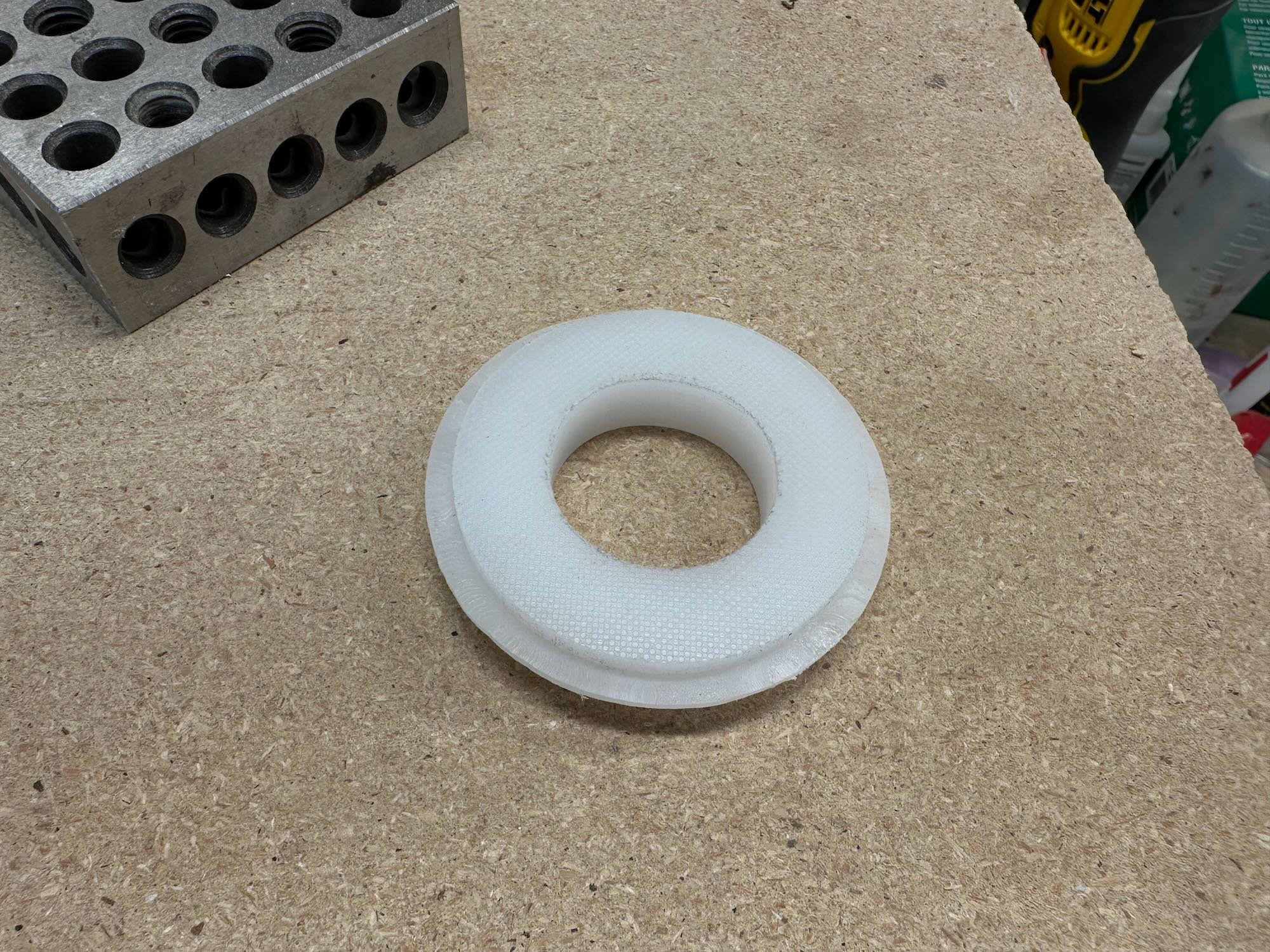
Probably the most crucial part of the carriage is a beveled teflon washer that surrounds the router bit. This is the part of the carriage that makes contact with the facing “up” part of the guitar body (Soundboard or back). The Teflon washer only has about ¼” ring that actually contacts the body. Since the router is on a roller carriage it moves up and down following the contour of the up facing part of the body, while the roller bearing on the Rabbet bit glides along the side of the body. I looked into purchasing an actual chunk of teflon but found it to be too expensive. Instead, I bought a cheap ¾” plastic cutting board and made the “Teflon” washer from it. While setting up the bit I learned I did not have a correct sized bearing for the bit to get the desired (shallow) depth I needed. To solve this problem I 3D designed/printed a thicker sleeve that press fitted over the bearing. This widened the bearing to the correct blade depth (2mm).

The second part of this jig is a body sled (#7). The body has to be secured in a way that aligns the “flatness” of the Soundboard/back and sides to relative squareness of the router/work surface. The sled assures the sides of the body are parallel to the router's up/down movement and provided a flat surface to slide against. The adjustable height brackets account for the un-flatness of the body. Correct placement is checked with a carpenters square holding one side of the square against the work surface and the other against the guitar body side. Squaring the body to the work surface is a bit of a dance between all four adjusters that requires multiple points of checking and adjustments.

To build the sled and adjusters, I use a scrap piece of MDF and 3D designed/printed the necessary L brackets and adjusters (#8). With all adjustments aligned the rabbet cut will be square to a relative 90° angle of the body (#9).


Conclusion

This was the most difficult to build jig for this project. All in all, it worked quite well. That said, I already have plans to build a 2.0 version which utilizes the Bosch Colt router (I already picked one up on a great black friday deal). The Colt has an adjustable platform design more suited for this jig. Hopefully, I will be able to create one that works as well AND is easier to adjust.

Building An Acoustic Guitar For The First Time - Part 4: A Guitar Shaped Box

Prepping For Closure

With all three body parts ready for assembly (#1), I made sure to sign my work on the underside of the Soundboard first, before I forgot (#2). I also decided to seal the inside of the body before closing it up (#3). 

I sealed the body and Soundboard after I attached the back to the sides. (It’s out of sequence because I only took photos of prepping the Soundboard). Prepping the back is exactly the same process. 

Regarding interior sealing: Amongst Luthiers there is some debate over sealing the inside. I am for sealing because it makes sense to have a moisture barrier and not raw wood. Also one of my favorite builders, Jeff Jewitt, is in the pro-sealing camp and if it’s good enough for him, well… you know the rest. I sealed it with CrystaLac It's “Knot” Shellac, mostly because it is what I had on hand. When sealing the Soundboard it’s important to be sure to not to add sealer where the glue joint is going to be.


Fitting and Gluing the Soundboard and Back

To fit the Soundboard/Back it first must be lined up accurately with the sides. Once I did this, I taped it down to alleviate movement. I marked the Soundboard and sides where the sides and braces meet (#4). Using the marks on the sides exterior I then transferred them to the inner kerfing by lining the marks up with a ruler (#5). 

I trimmed the brace ends to the correct length with a chisel (#6 and #7). That length equaled the distance from the outer marked lines minus the 2mm thickness of the sides. To cut the notch where the ends of the braces are inset to the kerfing, I used my rotary tool with a straight bit and depth gauge (#8). Afterward I cleaned up those notches with a chisel.

I attached the Back first because it can be seen easiest through the sound hole when the guitar is complete. Being able to clean up any glue squeeze-out is essential. When attaching the Soundboard it’s not quite as critical, since you cannot see the majority of it. With either though, care must be taken with the amount of glue you are using. Nobody likes a sloppy glue job.

I only took a photo of clamping the back (#9). I used the clamps I had on hand instead of buying or making speciality clamps for this procedure. The throats of my clamps were just barely long enough to fit over the mold but I managed to make it work.


Side Trimming

With the Soundboard and back attached the overhang needs to be trimmed off. (Photo #10 and #11 shows the Back trimmed but Soundboard not trimmed.) I used a handheld router and straight flush bit for trimming. It’s important to use a very sharp bit and to be careful in the areas where you're cutting against the grain. Those areas have the potential for tear out. 

Since a binding channel has to be cut into the edges there’s no need to worry about the router not being squared to the sides for this trimming. It does however, become important when cutting the binding channel.

Side Sanding

Remember the slight warpage I mentioned when I wrote about bending the sides? With the edges trimmed the sides can now be fully sanded flat as much as possible. There several ways to accomplish this, the two most common are using a cabinet scraper or a rolling-pin style sander. I don’t particularly like scraping wood so, I opted for this rolling-pin sander.

Side note: The actual spindle tool part of this sander is fine but the rubber sanding drums are slightly lumpy, which is not ideal for their application. The drums are the same dimensions of the drums for my table top spindle sander so I used those instead.

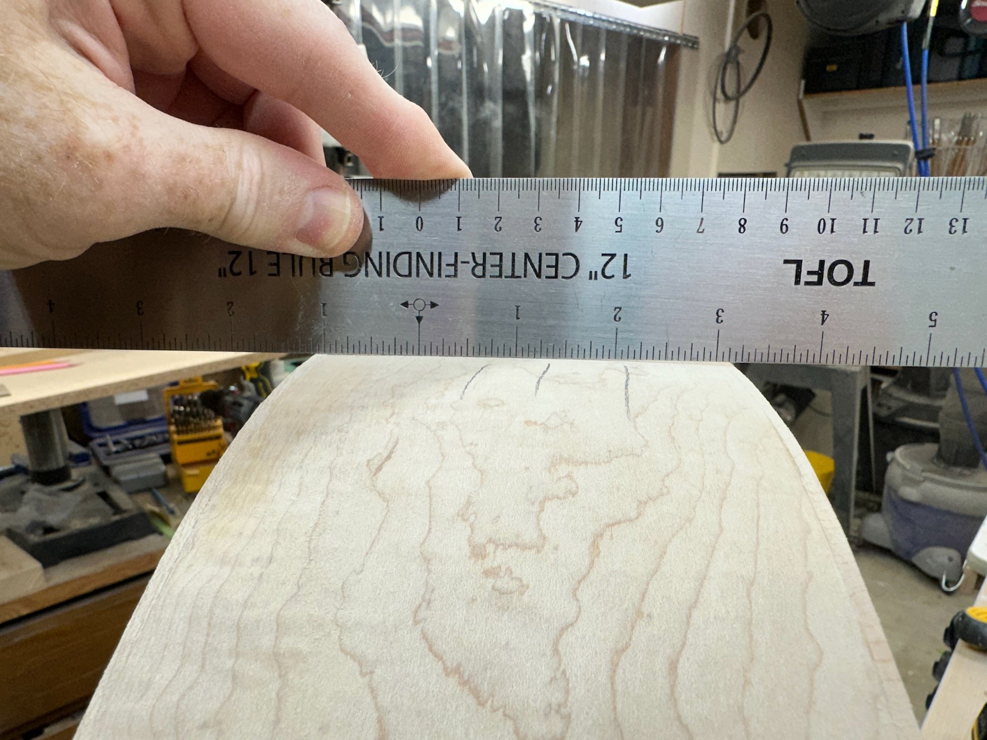
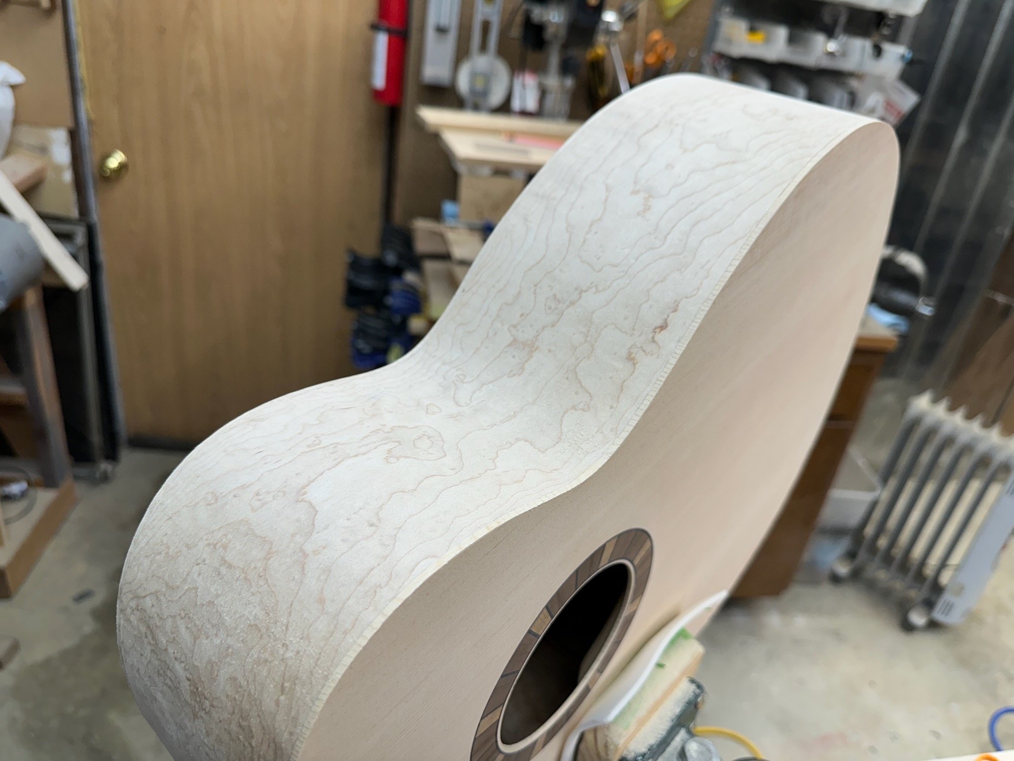
To sand the sides, I checked the flatness with a straight edge (#12) then marked the uneven spots (lightly) with a pencil (#13) and repeated the process as needed. Once finished, I achieved a reasonable amount of flatness (#14 and #15), although it was not perfectly flat in some areas. I doubt anyone would ever notice these areas without checking them with a straight edge. 

Oops…

It is important to note; it would be quite easy to sand through the sides (remember they’re only 2mm thick). I say this as a word of warning because I did just that. I accidentally sanded through a spot which unbeknownst to me was an area where the maple either had a massive ripple (I hadn’t seen) or had a defect. In an attempt to sand it out, I almost sanded through instead. I caught it before it went completely through the Maple but not soon enough for it to not be paper thin. The darker color of the Mahogany body was noticeable underneath. I did my best to repair it both inside and outside. The repair is okay and mostly blends in. I’m purposely not posting a closeup photo of it. I’d rather not point out the flaw, which in photos is probably not immediately noticeable

This mistake felt like a gut punch and made me rethink the project. I seriously considered scrapping the body and starting over. After much contemplation, I decide to forge ahead keeping in mind this entire build will have many mistakes and flaws and that’s okay. However, I still am not happy about it.


Only one more step to go before the body is complete and that is a big one: Binding.