Building An Acoustic Guitar For The First Time - Part 3: Side Bending

Shaping the Sides

Before bending the side panels I milled each down to the size of 2mm thick by 110mm wide with an overall length of 812mm (about 32”).

As I mentioned previously in Part 1 , there are several different ways you can bend wood. I opted for the steam and mold method.

The process is fairly simple, you steam the wood in a steam-box then clamp it onto a mold and wait for the wood to dry. The wood then retains the shape of the mold. 

My first attempt went well, initially. I soaked the panel in water for approximately 20 minutes then steamed it for 25 minutes. When I clamped the panel on the mold it bent easily and all seemed good (#1 and #2). I left it to dry in the mold overnight. 

When I removed the bent panel from the mold it retained the shape. Unfortunately, I immediately noticed a significant amount of perpendicular cupping and warpage, especially in the tightest curved portions near the waist of the curve (no photo).


Second Bending Attempt

After looking into the process of wood bending more, I decided the warping was probably caused by at least two factors. 

  • The irregular grain pattern of the Birdseye Maple is unstable and more prone to non-uniform warpage. 

  • The wood was too wet and did not dry out quickly enough. 

There was nothing I could do to address the first factor (other than use a different species). 

As for the second factor I made several changes. 

  • Decided not to pre-soak the wood.

  • Perforated the mold surface, to allow moisture an easier way to escape (#3).

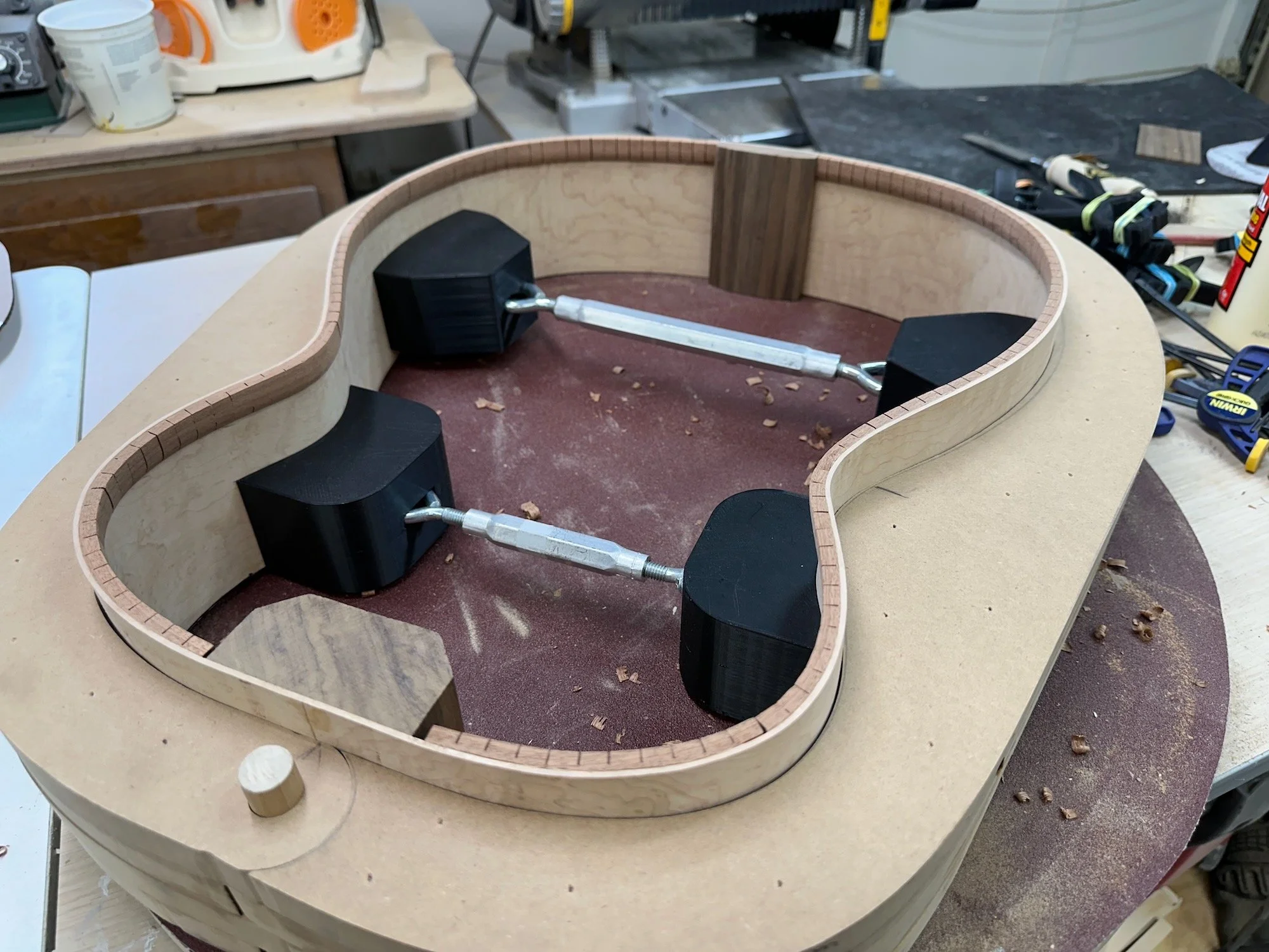
  • I 3D designed and printed top edge clamping molds that would hopefully keep the edges from curling/cupping (#4).

  • Use as many clamps as possible, along with the new edge mold, to “flatten” the wood perpendicularly (#5 and #6).

  • Leave the panel to dry on the mold longer. I chose a minimum of 48 hours.

Fortunately, these changes worked. The bent panel held its shape quite well (#7) and there was minimal warpage(#8). 

I did notice later though, over time, the waist areas had some perpendicular rippling, I’m assuming that was from the moisture further escaping. Overall though, it appeared to be such a minimal amount it could probably be corrected in the final stage of flat sanding the sides (once the top and bottom are attached.)


Trimming the Ends and Placing the Blocks

With the sides shaped and ready to go, the next step was to trim the ends to butt together so the top and bottom blocks could be glued in.

I first fit the sides into the full body mold for stability. Then I marked and cut the ends to fit flush with each other (#9). For cutting I used this Japanese Pull saw. To keep the cut angle consistent I use a solid 1-2-3 block with neodymium magnets attached to it (#10). I then clamp the 1-2-3 block down once the saw-blade is set up on the cut line (#11). The saw sticking to the block via the magnets ensures a straight and clean 90 degree cut with the freedom of sawing movement.

I made the top and back blocks from Walnut. The back block has to be shaped to match the inner curve against the rounded panels. Both blocks have to be shaped to the slight angle of the sound board and back on their respective ends (about 92 degrees).
The final sizes after shaping:

  • front block - 76mm(w) x 35(d) x 85(h) 

  • back block - 70mm(w) x 17(d) x 70(h)

I glued in the bottom block (#12) and the top block (#13). I left the blocks clamped in place to dry overnight (#14).


Creating the Radius Side Edging and Front Bout Taper

The front and back edges of the sides have to be trimmed to match the radius shapes of the Soundboard and Back. Additionally the side-taper on the Back at the upper bout (where the neck attaches) needs to be shaped. That taper drops 15mm compared to the overall edge height.

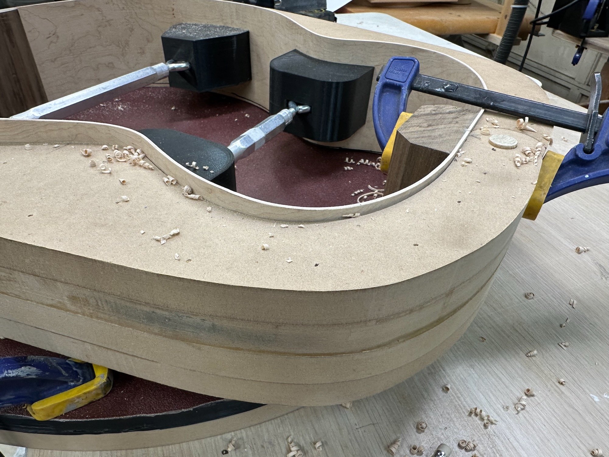
For side edge radius shaping it is common to set the sides (while still in the body mold) onto the radius, then turn or slide the sides back and forth allowing the radius shape to be formed by sanding the material away. This is similar to brace shaping (as explained earlier). This technique is commonly referred to as “driving the bus” (if the radius dish is on top it’s reminiscent of turning a large steering wheel).

With the amount of material needing removal I did not want to spend the amount of time and energy necessary to sand it all away. Instead, I opted to mark the radius line and then carve the majority off first with a hand plane/chisel.  

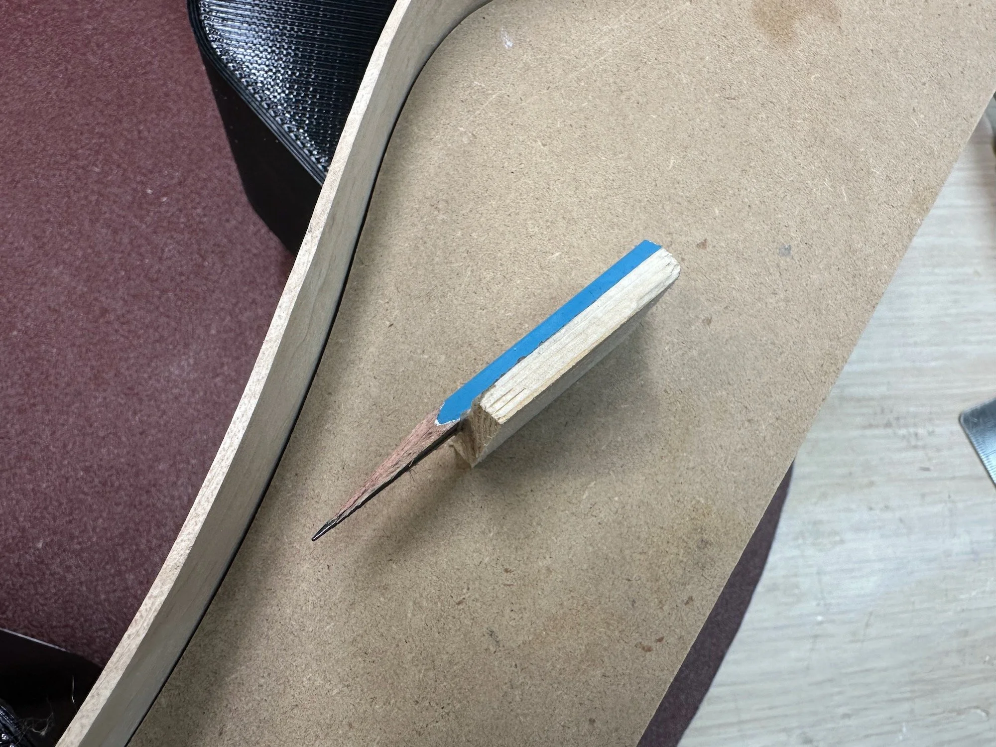
To mark the full radius shape I sat the sides (while in the mold) onto the radius dish. I then used a half flattened pencil attached to a block (#15) to scribe the line while sliding along the dish shape (#16). Since the dish is covered with sandpaper the block did not slide perfectly smooth but it worked well enough. If you’re wondering “why the block with the pencil?” The block is necessary due to a wide gap at the most curved portion that was taller than the pencil. The pencil has to be able to mark above that gap. I marked both edges of each side using their respective radius dishes. After removing the majority of the material with a plane/chisel I finished the final sanding by “driving the bus”.

For the upper bout taper shape, I eyeballed it by freehanding the tapered line on one side first (#17). I planed/chiseled the shape to the front center line.
To transfer the shape to the other side I used a tape pattern trick. I attached a piece of painters tape to the remaining area and traced the cut line to the tape (no photo). After cutting the tape on the line I carefully positioned the remaining tape on the opposite side to match (no photo). I drew the taper using the tape edge as a guide then proceeded to plane/chisel the second side to match the first side (#18).


Installing the Kerfing and Side Struts

With the sides all shaped I proceeded to make the kerfings from scrap Mahogany.

The size of the kerfing is 5.5mm x 17mm about 34 inches long. I first cut the kerfing strips on the table saw. I then tapered a half round edge using a hand plane and sandpaper. I cut the kerfing slots with my table saw using my narrow kerf fret blade. I installed the kerfings one half side at a time (#19, #20, #21) using a mix of squeeze clamps and rubber band clamps (3D printed using this file).

With the kerfings installed I added three Mahogany rectangular struts perpendicular to each side (#22, #23). With the glue dried I carved the struts with a chisel and cleaned them up with a round of sanding (#24, just like the soundboard braces).


That’s the finished sides! Next is assembling the Soundboard and Back to the sides.
Building An Acoustic Guitar For The First Time - Part 2: Soundboard and Back

Wood Selection

Before I get into the build details, I’d like to talk a little about my wood selection for this project. The most typical woods used for acoustics are Spruce for the top and Mahogany for the sides. Although those are the most common, just about any type of wood can be used. Like all things specialty, hardwoods can get quite expensive (high end Koa and Rosewood side and back sets can cost anywhere from $500 and up). I wanted to keep the costs as low as possible so I kept an eye out for medium grade woods that would not be terribly expensive. I also wanted to use quality woods even if they were not of the highest grade. The higher grade mostly has more to do with aesthetics (although some more desirable grain patterns can make a structural difference).

A few years ago, I got some great deals from my favorite hardwood supplier Kimball Hardwoods. I bought two Birdseye Maple body sets for $100 and a Sitka Spruce Top set for $50. They have been sitting and waiting in my wood library ever since. I am aware that most guitar building guides will dissuade you from using both Maple and figure woods for a guitar body. Both are considered more difficult to work with. Some builders/players also say a Maple body has less resonate, less deep sound compared to the darker hardwoods. I happen to love Maple and well a good deal is a good deal. Also, I was keen on the thought of having a couple of inexpensive sets to practice with for my first build. The neck will be made from Walnut. I have some Walnut in my wood library that I received for free and it just makes sense to use it. Plus, I think the contrast of a maple body and walnut neck will look sharp. I haven’t decided on the fretboard material yet. I have Ebony, Claro Walnut, Maple, Rosewood, Padauk and a couple others I’m probably forgetting all on hand. So I have some options and will eventually decide what combo looks best with the body and neck. I’m planning to use Walnut from the neck plank as the body binding, if I can make it work. I’ve done very little wood bending prior to this project.

If I haven’t mentioned it already, I’m not expecting this first guitar to be amazing. I see it as a test of the process of which I expect to encounter many mistakes. If I can get a reasonably good looking, sounding and playing instrument out of it, I’ll be happy. In short: good but not great, is my minimum goal.


Soundboard and Back Glue Up

I started the build by joining the top and back parts. I don’t have a jointer, so I cleaned up the center joint with a table saw trick I saw online. Unfortunately, I lost the link to the video. Basically you place the two halves together the way they will be glued. Temporarily hold them together by spanning a couple of scrap pieces of wood with double stick tape. Then set the cut to be dead center of the joint, and rip it down the center. Then glue up. It work quite well. After the glue joint dried I ran both planks through my drum sander. I sanded the back to an initial thickness of 3.5mm, with an eventual final thickness of 2.5mm. I sanded the front to an initial thickness of 3.5mm, with an eventual final thickness of 3mm. The photos are after glue up.

Disclaimer: Sometimes I get too focused in the shop and forget to take photos. I apologize that there will be steps along the way that have no photos.


The Rosette

I contemplated what the rosette design would be for quite a while. Ultimately I decided on a somewhat simple pattern utilizing two different wood species, Walnut and Roasted Maple as well as 1mm black veneer I had on hand. After laying out the pattern in Adobe Illustrator I imported the design into the laser cutting software (LightBurn) and cut a test to figure out the spacing and tolerances (#1). After tweaking some of the sizes I then laser cut the pattern out of the actual woods and painstakingly glued it all together (#2). This worked okay but without any backing, the pieces were difficult to keep together. I then realized if I taped at all together first from the back, I could dry-fit the pieces and easily add glue between the pieces (#3). Once that was done (#4) I taped it down to a flat board and ran it through the drum sander to level all of the pieces the same thickness (#5). I kept the final size around 3mm thick so It could be embedded proud of the soundboard then sanded down to match the final thickness of the soundboard at the same time. Finally, I finished up the final sizing by laser cutting the edges (#6). You will notice I also laser etched some added detail lines. Unfortunately I did not etch the lines deep enough and the lines were removed when I completed the final thickness sanding of the soundboard.

My next step was to inlay the completed rosette on the soundboard. I utilized my plunge router along with a circle jig and a straight 1/4” bit to make the circular dado for the inlay (#7). This process was pretty straight forward, if you’ve ever routed a circular dado. The hard part was figuring out the perfect size of the inside and outside of the rosette with the adjustable router jig. Not seen here are several waste boards I tested the sizing on. It took multiple minimal increment changes in order to get the sizing perfected so the two veneer strips and the rosette would fit snugly. Once I perfected the sizing it took 3-4 passes with the router to cut the full width of the dado. This photo shows one of those passes (#8). After I glued in the rosette using standard TiteBond, I ran the soundboard back through the drum sander using 220 grit paper and sanded it down to the final thickness (3mm).

Later, I discovered a spot where the edge of the rosette had a small gap. I repaired that gap by filling it with black Starbond CA glue and accelerator. I used frog tape to help keep the CA glue from staining the wood (#9, #10).

Once that was all cleaned up, I cut out the sound hole with the router and jig (#11, #12).


Bracing/Shaping the Soundboard and Back

Note: I made the Back/bracing prior to the Soundboard before I decided to blog this build. Consequently, I took very few photos of working on the Back. I’m writing more about the Soundboard but know the process for the Back is essentially the same. Also some of the photos will seem slightly out of order as I’m mixing the process together as I write about them.

The final step of the Soundboard involved making and placing the underside bracing. In order to place everything correctly I previously made a template based on the Kinkead design. I took a photo of the full sized printed plan that was included with the book, and sized it full scale in Adobe Illustrator. I then redrew the plan as a vector file and imported the design into Lightburn for laser cutting out of 1/4” plywood. All of the sizing for the bracing is marked on the template (#13).

The braces are made from Red Spruce I bought from American Tonewood. I cut the braces (end grain vertical) to size with an added 3-4 mm extra in height (#14). I rough cut the end curves with my bandsaw (no photo). The thin wide top strip bracing and blocks around the sound hole are offcuts from the top. The bridge brace is made from Walnut for extra strength.

When finished, the Soundboard and Back need to be slightly curved for rigidity. These curves are referred to as a Radius. The Soundboard will have a curve Radius of 25ft. the back Radius is 15ft. The concave radius dishes (I wrote about in Part 1) are utilized to achieve the Radius curves through shaping (sanding) and clamping (on the GoBar deck). Each of the Spruce braces have to be shaped to their respective radius curve. To accomplish this each dish is covered in sticky-back 80 grit sandpaper. The brace is then “sanded” back and forth on its back edge until the wood has been shaped into a matching curve (#15).

After all of the braces have been shaped they are glued to the Soundboard (or Back) while it is sitting on the radius dish. For clamping, the radius dish is placed on the bottom of the GoBar deck. The GoBar deck allows for clamping of multiple pieces on a curve. It applies pressure through the flexible struts onto the braces. That pressure pushes the Soundboard/Back into the radius shape. Once the glue has dried the Soundboard/Back retains the concave shaped of the dish (#16).

Note: Be aware of glue squeeze-out when clamping and be sure to have a cleanup solution at hand. For some of the pesky hard to reach joints, I used a utility knife blade to scrape off the wet unwanted glue.


Scalloping the Braces

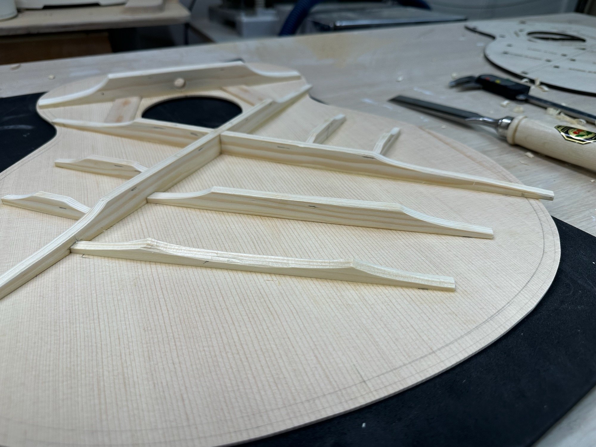
After the braces are glued in place they need to be carved into their final shape (#17). I used both a mini-hand plane and chisels to create the scallop shapes. The Spruce is carved fairly easily but I highly recommend well sharpened chisels to keep the work as clean as possible.

The shaping part of the process apparently aids in the resonance and voicing of the Soundboard. At this point you can tap the board and hear the response as material is removed. The Kinkead book refers to “listening out for the dropping of pitch”. I think I heard it along the way. I’m not really sure though as I don’t have any experience to compare it to.

I was well underway with the scalloping when I realized I had forgotten to add a small ridge cap over the x-brace joint. Fortunately, I hadn’t fully carved that area yet so I was able to add the cap (#18.)

Once the carving was done I smoothed all of the braces out by sanding first with 80 grit paper I then finished with a pass of 120 grit and finished with 220 grit (#19., #20.)


That’s all for the Soundboard and Back. Next will be all about shaping the Sides.